Tuesday 29 October 2019

Electrical Circuits and Thevenin’s theorem:

Thevenin’s theorem:


Thevenin’s theorem states that any two terminal linear network or circuit can be represented with an equivalent network or circuit, which consists of a voltage source in series with a resistor. It is known as Thevenin’s equivalent circuit. A linear circuit may contain independent sources, dependent sources, and resistors.
If the circuit contains multiple independent sources, dependent sources, and resistors, then the response in an element can be easily found by replacing the entire network to the left of that element with a Thevenin’s equivalent circuit.
The response in an element can be the voltage across that element, current flowing through that element, or power dissipated across that element.
This explains the Thevenin's theorem.
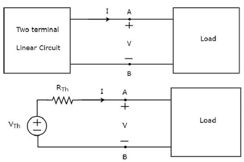
Response in Element

Thevenin’s equivalent circuit resembles a practical voltage source. Hence, it has a voltage source in series with a resistor.
The voltage source present in the Thevenin’s equivalent circuit is called as Thevenin’s equivalent voltage or simply Thevenin’s voltage, VTh.
The resistor present in the Thevenin’s equivalent circuit is called as Thevenin’s equivalent resistor or simply Thevenin’s resistor, RTh.


  Thevenin's  Theorem Procedure:

 1. Remove that portion of the network where the Thevenin's equivalent circuit is found.  This requires that the load resistor RL be temporarily removed from the network.
2. Mark the terminals of the remaining two-terminal network. (The importance of this step will become obvious as we progress through some complex networks.) RTh:
 3. Calculate RTh by first setting all sources to zero (voltage sources are replaced by short circuits and current sources by open circuits) and then finding the resultant resistance between the two marked terminals. (If the internal resistance of the voltage and/or current sources is included in the original network, it must remain when the sources are set to zero.) ETh:
 4. Calculate ETh by first returning all sources to their original position and finding the open-circuit voltage between the marked terminals. 

Conclusion: 5. Draw the Thevenin's equivalent circuit with the portion of the circuit previously removed replaced between the terminals of the equivalent circuit. This step is indicated by the placement of the resistor RL between the terminals of the Thevenin's equivalent circuit as shown .

 EXAMPLE:Convert the circuit shown in Fig, to a single voltage source in serieswith a single resistor.   


Solution. Obviously, we have to find equivalent Thevenin's circuit.
For this purpose, we have to calculate 


(i) Vth or VAB and (ii) Rth or RAB .
With terminals A and B open,the two voltage sources are connected in subtractive series because they oppose each other.Net voltage around the circuit is
(15 − 10) = 5 V and

total resistance is (8 + 4) = 12 Ω.

 Hence circuit current is = 5/12 A. 

Drop across 4Ω resistor = 4 × 5/12 = 5/3 V with  the polarity as shown in Fig. 

∴ VAB = Vth = + 10 + 5/3 = 35/3 V.


Incidently, we could also find VAB while going along the parallel route BFEA.
Drop across 8 Ω resistor = 8 × 5/12 = 10/3 V. VAB equal the algebraic sum of voltages met on the way from B to A. Hence, VAB = (− 10/3) + 15 = 35/3 V.
As shown in Fig. , the single voltage source has a voltage of 35/3 V.
To finding R th , we will replace the two voltage sources by short-circuits. In that case, Rth = R AB
= 4 || 8 = 8/3 Ω.


No comments:

Post a Comment

Star to Delta and Delta to Star Transformations:

Star to Delta and Delta to Star Transformations:  In a pattern series and parallel connections , electrical components may be connected...