Friday, 1 November 2019

INTRODUCTION TO ELECTRICAL CIRCUITS -1 , Concept of Network and circuit , Types of Elements,Types of Sources

INTRODUCTION TO ELECTRICAL CIRCUITS -1

•Concept of Network and circuit

•Types of Elements

•Types of Sources

•Source Transformation

•R-L-C Parameters

•Voltage -Current relationships for Passive Elements 


INTRODUCTION: 

An Electric circuit is an inter-connection of various element's in which there is at least one closed path in which current can flow. An Electric circuit is used as a component for any engineering system.The performance of any electrical device or machine is always studied by drawing its electrical equivalent circuit. By simulating an electric circuit, any type of system can be studied for ex., mechanical, hydraulic thermal, traffic flow, weather prediction etc.All control systems are studied by representing of  them in the form of electric circuits. The analysis, of any system can be learnt by mastering the techniques of circuit theory. 

Elements of an Electric circuit:

 An Electric circuit consists of following types of elements. 

Active elements: 

Active elements are the elements of a circuit which possess energy of their own and can impart it to other element of the circuit.Active elements are of two types 

a) Voltage source    b) Current source 

     A Voltage source has a specified voltage across its terminals, independent of current flowing through it.

  A current source has a specified current through it independent of the voltage appearing across it.


Passive Elements: 

 The passive elements of an electric circuit do not possess energy of their own. They receive energy from the sources. The passive elements are the resistance, the inductance and the capacitance. 

 When electrical energy is supplied to a circuit element, it will respond in one and more of the following ways. 

If the energy is consumed or dissipated, then the circuit element is a pure resistor.
 If the energy is stored in the form of a magnetic field, the element is a pure inductor.
 And if the energy is stored in the form of an electric field, the element is a pure capacitor.

Linear and Non-Linear Elements:

 Linear elements show the linear characteristics of the voltage & current. That is its voltage-current characteristics are at all-times a straight-line through the origin.

 For example, the current passing through a resistor is proportional to the voltage applied through its and the relation is expressed as VI or V = IR. A linear element or network is one which satisfies the principle of superposition, i.e., the principle of homogeneity and additive.

 Resistors, inductors and capacitors are the examples of the linear elements and their properties do not change with a change in the applied voltage and the circuit current. 

   Non linear element’s V-I characteristics do not follow the linear pattern i.e. the current passing through it does not change linearly with the linear change in the voltage across it. Examples are the semiconductor devices such as diode, transistor.

Bilateral and Unilateral Elements: 

An element is said to be bilateral, when the same relation exists between voltage and current for the current flowing in both directions.Ex: Voltage source, Current source, resistance, inductance & capacitance.The circuits containing them are called bilateral circuits.

 An element is said to be unilateral, when the same relation does not exist between voltage and current when current flowing in both directions. The circuits containing them are called unilateral circuits.Ex: Vacuum diodes, Silicon Diodes, Selenium Rectifiers etc .

Lumped and Distributed Elements Lumped elements:

 Lumped elements are those elements which are very small in size & in which their simultaneous actions takes place. Typical lumped elements are capacitors, resistors, inductors. 

Distributed elements are those which are not electrically separable for analytical purposes.For ex: a transmission line has distributed parameters along its length and may extend for hundreds of Kms.

Types of Sources: 

Independent & Dependent sources: 

If the voltage of the voltage source is completely independent source of current and the current of the current source is completely independent of the voltage, then the sources are called as independent sources. 

The kind of sources in which the source voltage or current depends on some other quantity in the circuit which may be either a voltage or a current anywhere in the circuit are called Dependent sources or Controlled sources.

 There are four possibility dependent sources: 

a.Voltage dependent Voltage source 

b.Current dependent Current source 

c.Voltage dependent Current source

 d.Current dependent Current source


 The constants of proportionalities are written as B, g, a, r in which B & a has no units,
r has units of ohm & g units of mho . 

 Independent sources actually exist as physical entities such as battery, a dc generator & an alternator. But dependent sources are used to represent electrical properties of electronic devices such as diode,Transistors etc.,


Ideal & Practical sources: 

1.An ideal voltage source is one which delivers energy to the load at a constant terminal voltage, irrespective of the current drawn by the load at any time.

 2.An ideal current source is one, which delivers energy with a constant current to the load, irrespective of the terminal voltage across the load at any time. 

3.A Practical voltage source always possesses a very small value of internal resistance r. The internal resistance of a voltage source is always connected in series with it & for a current source; it is always connected in parallel with it.As the value of the internal resistance of a practical voltage source is very small, its terminal voltage is assumed to be almost constant within a certain limit of current flowing through the load.

 4.A practical current source is also assumed to deliver a constant current, irrespective of the terminal voltage across the load connected to it.


The equivalent single ideal voltage sum is given by V= V1 + V2 

   Any n number of ideal voltage sources connected in series can be represented by a single ideal voltage sum taking in to account the polarities connected together in to consideration.


When two ideal voltage sources are of e.m.f's V1 & V2 are connected in parallel,what voltage appears across its terminals is ambiguous.Hence such connections should not be made.However if V1 = V2= V, then the equivalent voltage sum is represented by V.In this case also, such a connection is unnecessary as only one voltage source serves the purpose.


When ideal current sources are connected in series, what current flows through the line is ambiguous. Hence such a connection is not permissible.However, it I1 = I2 = I, then the current in the line is I.But, such a connection is not necessary as only one current source serves the purpose.


Two ideal current sources in parallel can be replaced by a single equivalent ideal current source.


Thursday, 31 October 2019

Norton’s theorem:

Norton’s theorem:

Norton's theorem in Any two-terminal linear bilateral dc network can be replaced by an equivalent circuit consisting of a current source and a parallel resistor,


Thevenin’s theorem with respect to the equivalent circuit can also be applied to the Norton equivalent circuit. The steps leading to the proper values of IN and RN are now listed.

Norton’s Theorem Procedure :
 1. Remove that portion of the network across which the Norton equivalent circuit is found.
 2. Mark the terminals of the remaining two-terminal network .


Converting between Thevenin's and Norton equivalent circuits

3. Calculate RN by first setting all sources to zero (voltage sources are replaced with short circuits and current sources with open circuits) and then finding the resultant resistance between the two marked terminals. (If the internal resistance of the voltage and/or current sources is included in the original network, it must remain when the sources are set to zero.) Since RN = RTh, the procedure and value obtained using the approach described for Thevenin’s theorem will determine the proper value of RN

4. Calculate IN by first returning all sources to their original position and then finding the short-circuit current between the marked terminals. It is the same current that would be measured by an ammeter placed between the marked terminals.

5. Hence,Draw the Norton equivalent circuit with the portion of the circuit previously removed replaced between the terminals of the equivalent circuit.

Tuesday, 29 October 2019

Electrical Circuits and Thevenin’s theorem:

Thevenin’s theorem:


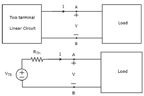
Thevenin’s theorem states that any two terminal linear network or circuit can be represented with an equivalent network or circuit, which consists of a voltage source in series with a resistor. It is known as Thevenin’s equivalent circuit. A linear circuit may contain independent sources, dependent sources, and resistors.
If the circuit contains multiple independent sources, dependent sources, and resistors, then the response in an element can be easily found by replacing the entire network to the left of that element with a Thevenin’s equivalent circuit.
The response in an element can be the voltage across that element, current flowing through that element, or power dissipated across that element.
This explains the Thevenin's theorem.

Response in Element

Thevenin’s equivalent circuit resembles a practical voltage source. Hence, it has a voltage source in series with a resistor.
The voltage source present in the Thevenin’s equivalent circuit is called as Thevenin’s equivalent voltage or simply Thevenin’s voltage, VTh.
The resistor present in the Thevenin’s equivalent circuit is called as Thevenin’s equivalent resistor or simply Thevenin’s resistor, RTh.


  Thevenin's  Theorem Procedure:

 1. Remove that portion of the network where the Thevenin's equivalent circuit is found.  This requires that the load resistor RL be temporarily removed from the network.
2. Mark the terminals of the remaining two-terminal network. (The importance of this step will become obvious as we progress through some complex networks.) RTh:
 3. Calculate RTh by first setting all sources to zero (voltage sources are replaced by short circuits and current sources by open circuits) and then finding the resultant resistance between the two marked terminals. (If the internal resistance of the voltage and/or current sources is included in the original network, it must remain when the sources are set to zero.) ETh:
 4. Calculate ETh by first returning all sources to their original position and finding the open-circuit voltage between the marked terminals. 

Conclusion: 5. Draw the Thevenin's equivalent circuit with the portion of the circuit previously removed replaced between the terminals of the equivalent circuit. This step is indicated by the placement of the resistor RL between the terminals of the Thevenin's equivalent circuit as shown .

 EXAMPLE:Convert the circuit shown in Fig, to a single voltage source in serieswith a single resistor.   


Solution. Obviously, we have to find equivalent Thevenin's circuit.
For this purpose, we have to calculate 


(i) Vth or VAB and (ii) Rth or RAB .
With terminals A and B open,the two voltage sources are connected in subtractive series because they oppose each other.Net voltage around the circuit is
(15 − 10) = 5 V and

total resistance is (8 + 4) = 12 Ω.

 Hence circuit current is = 5/12 A. 

Drop across 4Ω resistor = 4 × 5/12 = 5/3 V with  the polarity as shown in Fig. 

∴ VAB = Vth = + 10 + 5/3 = 35/3 V.


Incidently, we could also find VAB while going along the parallel route BFEA.
Drop across 8 Ω resistor = 8 × 5/12 = 10/3 V. VAB equal the algebraic sum of voltages met on the way from B to A. Hence, VAB = (− 10/3) + 15 = 35/3 V.
As shown in Fig. , the single voltage source has a voltage of 35/3 V.
To finding R th , we will replace the two voltage sources by short-circuits. In that case, Rth = R AB
= 4 || 8 = 8/3 Ω.


Super Position Theorem:

Theorems:

 Super Position Theorem:

  Super Position Theorem that current through, or voltage across, any element of a network is equal to the algebraic sum of the currents or voltages produced independently by each source.

     In other words, this theorem allows us to find a solution for a current or voltage using only one source at a time. Once we have the solution for each source, we can combine the results to obtain the total solution. The term algebraic appears in the above theorem statement because the currents resulting from the sources of the network can have different directions, just as the resulting voltages can have opposite polarities. If we are to consider the effects of each source, the other sources obviously must be removed. Setting a voltage source to zero volts is like placing a short circuit across its terminals. Therefore, when removing a voltage source from a network schematic, replace it with a direct connection (short circuit) of zero ohms. Any internal resistance associated with the source must remain in the network. Setting a current source to zero amperes is like replacing it with an open circuit. Hence, when removing a current source from a network schematic, replace it by an open circuit of infinite ohms. Any internal resistance associated with the source must remain in the network


Removing a voltage source and a current source to satisfy the superposition theorem.


Since the effect of each source will be determined independently, the number of networks to be analyzed will equal the number of sources.

      If a particular current of a network is to be determined, the contribution to that current must be determined for each source. When the effect of each source has been determined, those currents in the same direction are added, and those having the opposite direction are subtracted; the algebraic sum is being determined. The total result is the direction of the larger sum and the magnitude of the difference. Similarly, if a particular voltage of a network is to be determined, the contribution to that voltage must be determined for each source. When the effect of each source has been determined, those voltages with the same polarity are added, and those with the opposite polarity are subtracted; the algebraic sum is being determined. The total result has the polarity of the larger sum and the magnitude of the difference.


Example:

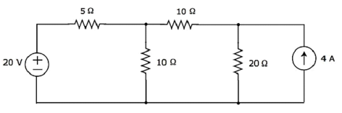
calculate  the current flowing through 20 Ω resistor of the following circuit using superposition theorem.

Superposition Theorem
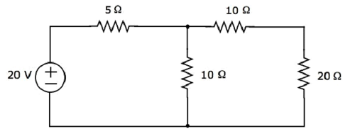
Step 1 − Let us calculate the current flowing through 20 Ω resistor by considering only 20 V voltage source. In this case, we can eliminate the 4 A current source by making open circuit of it. The modified circuit diagram is shown below.
Voltage Source
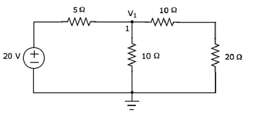
There is only one principal node except Ground in the above circuit. So, we can use nodal analysis method. The node voltage V1 is labelled in the following figure. Here, V1 is the voltage from node 1 with respect to ground.
Nodal
The nodal equation at node 1 is


The current flowing through 20 Ω resistor can be found by doing the following simplification.


Substitute the value of V1 in the above equation.


Therefore, the current flowing through 20 Ω resistor is 0.4 A, when only 20 V voltage source is considered.
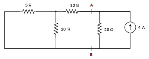
Step 2 − Let us find the current flowing through 20 Ω resistor by considering only 4 A current source. In this case, we can eliminate the 20 V voltage source by making short-circuit of it. The modified circuit diagram is shown in the following figure.
Current Source
In the above circuit, there are three resistors to the left of terminals A & B. We can replace these resistors with a single equivalent resistor. Here, 5 Ω & 10 Ω resistors are connected in parallel and the entire combination is in series with 10 Ω resistor.
The equivalent resistance to the left of terminals A & B will be


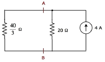
The simplified circuit diagram is shown in the following figure.
Figure
We can find the current flowing through 20 Ω resistor, by using current division principle.


Substitute IS=4A,  and  in the above equation.


Therefore, the current flowing through 20 Ω resistor is 1.6 A, when only 4 A current source is considered.
Step 3 − We will get the current flowing through 20 Ω resistor of the given circuit by doing the addition of two currents that we got in step 1 and step 2. Mathematically, it can be written as


Substitute, the values of I1 and I2 in the above equation.


Therefore, the current flowing through 20 Ω resistor of given circuit is 2 A.
Note − We can’t apply superposition theorem directly in order to find the amount of power delivered to any resistor that is present in a linear circuit, just by doing the addition of powers delivered to that resistor due to each independent source. Rather, we can calculate either total current flowing through or voltage across that resistor by using superposition theorem and from that, we can calculate the amount of power delivered to that resistor using  or .

Star to Delta and Delta to Star Transformations:

Star to Delta and Delta to Star Transformations:  In a pattern series and parallel connections , electrical components may be connected...